uninterruptible power supply circuit diagram
The resistive load used to understand the working principle. Uninterruptible power supply also used in many countries where energy shortage is a main issue.

3 Simple Ups Circuits Uninterruptible Power Supply Diagram Eleccircuit Uninterruptible Power Supply Circuit Diagram Circuit
The circuit shows that only two rooms of the home are depends on the UPS and Batteries as well as main supply to maintain the uninterruptible power to the connected appliances and load such as lighting points and.

. A switch is embedded to provide extra control along with an LED to indicate the energizing of the module. Click image to enlarge. It causes a voltage drop.
You connect it to a 12V battery. The breadboard power supply module consists of. Modern personal computers universally use switched-mode power suppliesSome power supplies have a manual switch for selecting input voltage while others automatically adapt to the mains voltage.
Regulated Power Supply Uninterruptible Power Supply As the type changes. A lot of 6V supply diagrams. Most modern desktop personal computer power.
The Arduino Uno is really a microcontroller board based on the ATmega328. Recently there was short circuit in the transformer feeding power to our school and few homes around. The mentioned functional stages of an uninterruptible power supply unit could be understood in detail through the following block diagram.
When equipment is attached to the supply the added drop is fairly small and the regulation is improved. It will be damaged. Buck-boost transformers sometimes used as push-pull transformers are a type of transformer that is used to supply power to electrical equipment in cases when the voltage requirements of that equipment are different from the available line or supply voltageThe need to raise the supply voltage might result from a drop in line voltage due to equipment demand on.
An example of a power system is the electrical grid that provides power to homes and industries within an extended area. The DC power port and USB-A connector are provided to the module to power it up. The short circuit was caused by group of squirrels.
An uninterruptible power supply UPS uses battery and inverter. The design basically utilizes a common collector or an emitter follower topology for implementing the operations by incorporating just a few Darlington power transistors some resistors and a pot. In the diagram above taking an installation without an isolation transformer the device has an earth fault for example a live conductor has shorted to the chassis.
The power inverter used in the HVDC. Please refer this link to know more about Uninterruptible Power Supply Circuit Diagram and Working. The ControlLogix controllers are modular and consist of a power supply processor chassis communication modules andor.
I have also added practical circuit for UPS in this article. Additional wiring connection with connected load and appliances for two rooms in home. The electrical grid can be broadly divided into the generators that supply the power the transmission system that carries the power from the.
Here we can see that the main UPS changeover function is carried out by a couple of DPDT relay stages. 12V to 6V Converter circuits Your load is too hot. This is the circuit diagram of the mobile phone charger.
A power supply unit PSU converts mains AC to low-voltage regulated DC power for the internal components of a computer. Both the DPDT relays are powered from a 12 V AC to DC power supply or adapter. DC UPS - 12V.
715 and 716 present the block diagram of the SMPS. When rectified this results in the pattern shown in the diagram with peaks of 339V and valleys of 0V. It will become so time-consuming to understand the basic structure but with the help of circuit symbols and diagrams it is easy to analyze the structure of a charger.
Power Port USB Port. Typically an AC power supply acquires the voltage from the mains supply and the voltage can be step up or step down by using a transformer to the required voltage and some filtering may take place. Jul 18 2022 By.
6 0-50V Variable supply 3A. Assume the terminal voltage of a power supply is 30 volts with no load resistor. An electric power system is a network of electrical components deployed to supply transfer and use electric power.
UPS uninterruptible power supply Automotive Description The STWD100 watchdog timer circuits are self-contained devices which prevent system failures that are caused by certain types of hardware errors such as non-responding peripherals and bus contention or software errors such as a bad code jump and a code stuck in loop. Energy and Power Key points on how to design a fault-tolerant and reliable facility distribution system. Uninterruptible power supply have very core importance for control of sensitive devices such as computers induction machines medical equipments and many other things.
Power Switch LED. A very straightforward circuit design for the proposed 100 amp variable voltage power supply can be witnessed in the following diagram. How to Connect Automatic UPS Inverter to the Home Supply System.
It has 14 digital inputoutput pins of which 6 may be employed as PWM outputs 6 analog inputs a 16 MHz crystal oscillator a USB connection a power jack an ICSP header along with a reset. Here the Arduino UNO schematic diagram click to enlarge. Switch Mode Power Supply SMPS Uninterruptible Power Supply UPS UPS is a Backup power source that in.
0-30v variable power supply circuit diagram. The supply voltage divides into two equal parts. It can be inserted anywhere in a 24VAC system to charge a battery and supply an uninterruptible 24VAC to.
The below fig 3 shows that how to connect a UPS Inverter with batteries to the Main Distribution Unit for continues power supply in case of the utility power failure. The mb102 breadboard supply module is capable of giving out 33 volts or 5 volts to. Today the SMPSs provide power to the following equipment.
It can get 6V only. How to Connect a Portable Generator to the Home Supply 4 Methods Below is a given UPS Inverter connection and wiring diagram to the home supply. Due to short circuit.
The load resistor acts as a preload on the power supply. Voltage Regulation Example 2. No equipment is connected to it.
A switched-mode power supply SMPS is a power electronics topology which consists of two power stages. Regardless of how reliable the individual power-system components may be some sort of power-system redundancy is necessary to attain high levels Read more. If you do not want this to you.
Nowadays power system reliability is more important than ever. Now see if we make our draft with words. The different types of AC.
3 AC Power Supply. The power supply circuits are classified into different types based on the power they utilize for providing for circuits or devices. It is also sometimes used to synchronize the thermostats internal clock and supply power for electronics and pilot lights.
The first stage converts the ac supply into dc and the second stage converts the dc voltage to the desired dc output voltage. Power Supply Block Diagram The Power supply circuit is used in various electrical electronic devices. 1203 Communication Modules 140G MCB 140U MCB 1492 Wiring System 1496 Timers 1606 Switched Mode Power Supplies 1609 Uninterruptible Power Supplies 1715 Redundant IO 1719 Ex IO 1732 ArmorBlock 1760 Pico.
Two thyristors S1 and S2 connected with two feedback diodes D1 and D2 as shown in the below circuit diagram.

600 Watts Ups Circuit Power Supply Circuits Uninterruptible Power Supply Power Supply Circuit Power Supply

Simple Dc Ups Circuit For Modem Router Homemade Circuit Projects Circuit Projects Electronic Circuit Projects Modem Router
Types Of Uninterruptible Power Supply Devices With Working Circuit Diagram Electrical Circuit Diagram Uninterruptible Power Supply

Automatic Micro Ups Circuit Uninterruptible Power Supply Circuit Projects Electronic Circuit Projects

4 Simple Uninterruptible Power Supply Ups Circuits Explored Homemade Circuit Proj Electronic Circuit Projects Circuit Projects Uninterruptible Power Supply

Ups Uninterruptible Power Supply You Will Learn What Is Ups How To Make Practical Ups I Have Also A Uninterruptible Power Supply Power Supply Circuit Ups

4 Simple Uninterruptible Power Supply Ups Circuits Explored Homemade Circuit Projects Circuit Projects Uninterruptible Power Supply Circuit
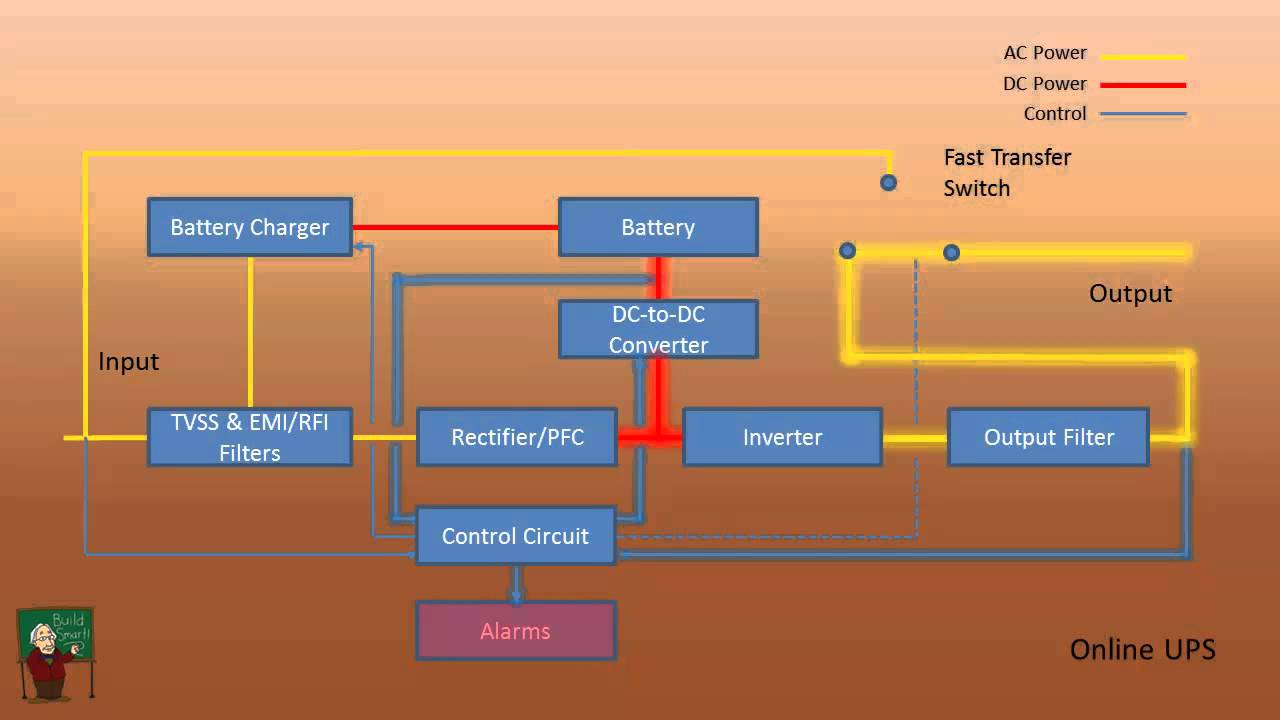
How A Ups Works Online Ups Circuit Diagram Uninterruptible Power Supplies

In The Following Article We Discuss 3 Useful Dc To Dc Uninterruptible Power Supply Circuits Or Dc Ups Circ Electronic Circuit Projects Circuit Circuit Projects

How To Make A Simplest 200 Va Uninterrupted Power Supply Ups Circuit Circuit Projects Uninterruptible Power Supply Electronic Circuit Projects

3 Simple Ups Circuits Uninterruptible Power Supply Diagram Eleccircuit Circuit Power Uninterruptible Power Supply

3 Simple Dc Ups Circuits For Modem Router Homemade Circuit Projects Circuit Projects Modem Router Modem

Mini Circuit Projects Timer Circuits Emergency Light Hobby Circuits The Article Details A Simple Transistor Based Ups C Circuit Projects Ups Electronics Basics

How To Design An Uninterruptible Power Supply Ups Circuit Homemade Circuit Projects

Data Center Design Consideration Ups Data Center Design Data Center Data

3 Simple Ups Circuits Uninterruptible Power Supply Diagram Eleccircuit

In This Article We Discuss A 1000 Watt Ups Circuit Powered With A 220v Input Us Circuit Projects Electronic Circuit Projects Uninterruptible Power Supply

Uninterrupted Power Supply

600 Watts Ups Circuit Uninterruptible Power Supply Power Supply Circuit Power Supply
No comments for "uninterruptible power supply circuit diagram"
Post a Comment